All signals experience random fluctuations in phase, a phenomenon referred to as phase noise. This...
The number of low Earth orbit (LEO) satellite deployments continues to grow significantly. These systems must undergo thorough testing to meet strict specifications and perform as expected.
This post reviews important measurements and test instrument capabilities when analyzing the uplink and downlink paths of satellite communications networks.
Path Delay & 5G TDD Network Timing
Satellite networks used for 5G communications will utilize time division duplexing (TDD), which relies on fast uplink and downlink switching. Faulty switching components or network latency can cause an overlap between uplink/downlink transmissions, reducing network performance.
Power sensors with quick rise time capabilities are able to characterize the response time of 5G TDD switches, while fast measurement speed captures latency at various points along the communications path. Ideal for 5G TDD satellite network testing, Boonton RTP5000 Series Real-Time USB Peak Power Sensors have 3 nanosecond rise times, utilize Real-Time Power Processing (RTPP), produce 100,000 measurements per second, and can resolve a nanosecond time difference between switching components.
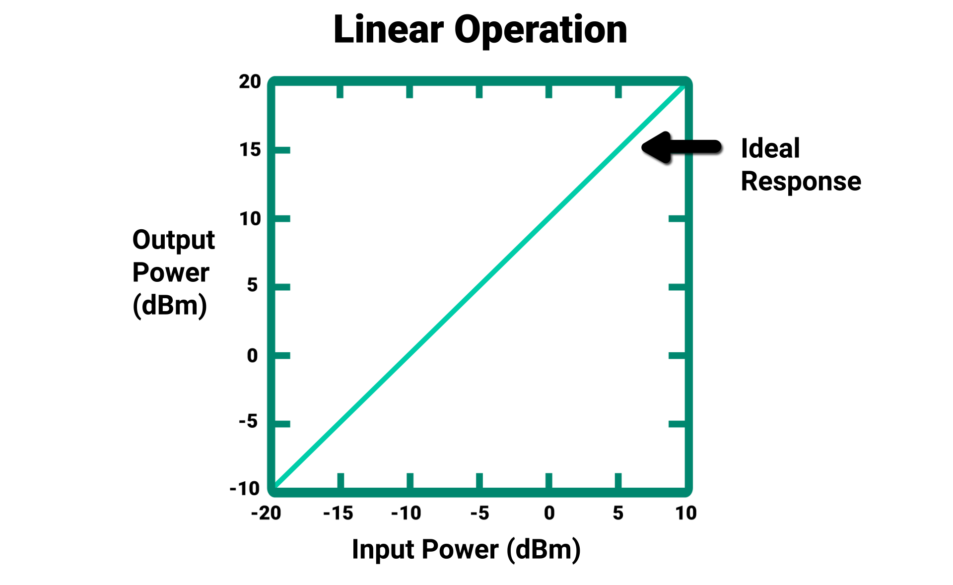
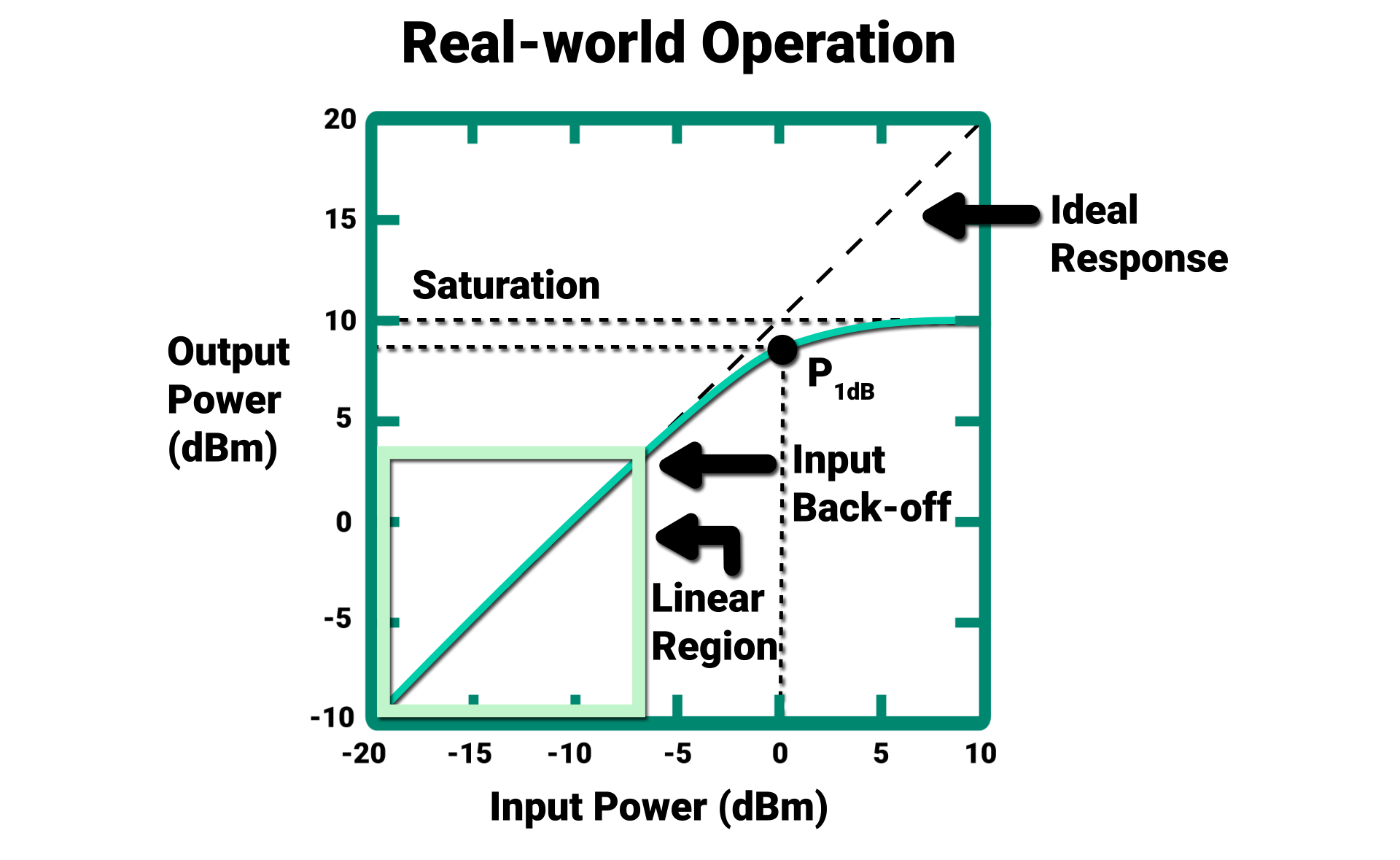
Determining Amplifier Linearity
There are several ways to test the linearity of amplifiers used in satellite networks. One method involves comparing the crest factor (CF) of an amplifier’s input and output signals, measured using peak power sensors. The CF and statistical analysis (i.e., CCDF) capabilities of the RTP5000 Series can quickly establish if amplifiers are being driven into compression.
Alternatively, the noise power ratio (NPR) method passes a notched, band-limited noise signal through an amplifier. Since intermodulation distortion (IMD) will accumulate at the notch frequency, observing the change in notch depth will reveal linear or nonlinear behavior. The Noisecom UFX7000B Programmable Noise Generator can produce the exact noise signal needed for NPR testing.
Response to RF Interference & Jitter Measurements
RF interference is everywhere, meaning satellite systems must be designed to operate in congested wireless environments. By generating highly controllable and customizable additive white Gaussian noise (AWGN) signals, satellite network designers can test the response of their satellite uplink/downlink paths when exposed to interference that mimics the real world.
To create the desired noise output, instruments like the UFX7000B offer a high level of control over filtering, switches, and attenuation (0.1 dB steps over 127 dB dynamic range).
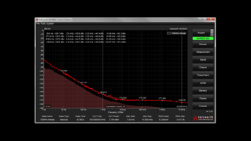
Jitter, which refers to a signal’s deviations in time, can increase as noise levels rise. The Holzworth HA7062 Series Real-Time Phase Noise Analyzers are ideal for measuring jitter and phase noise which, if excessive, will negatively affect network performance.
Phase Noise Analysis & LO Substitution
Satellite networks using higher order modulation schemes benefit from faster data rates, but at the cost of susceptibility to phase noise. One potential phase noise contributor are the satellite system’s local oscillators (LOs). High-performance phase noise analyzers are ideal for measuring an LO’s absolute phase noise, as well as the additive phase noise of a signal traveling through the network.
Replacing the LO with a signal source that generates a clean output can confirm the LO’s poor performance and avoid the LO characteristics from influencing the testing of up/downconverter chains. The Holzworth HSX9000 Series Multi-Channel RF Synthesizer acts as an excellent LO substitute, producing signals with exceptionally low phase noise.


Characterizing Antenna Performance
Peak power sensors can simplify satellite communications testing by analyzing antenna performance. By measuring a signal’s incident power and the reflected power from the antenna, designers can calculate return loss to test and validate performance.
Antennas radiate energy into space. Antenna gain pattern measurements use peak power sensors to determine the radiation’s beam pattern, uncovering the signal strength of pulsed or CW signals that an antenna radiates in the desired direction and checking that radiation in undesired directions is minimized.
SATELLITE 2023 Demonstration: Satellite Uplink & Downlink Testing
Whether measuring propagation delay, 5G TDD network timing, noise tolerance, satellite amplifier linearity, phase noise, or antenna performance, Wireless Telecom Group solutions are ideal for testing physical layer subsystems in the uplink and downlink paths of satellite communications networks.
At SATELLITE 2023, a premiere conference for the space and satellite communities, Wireless Telecom Group will show examples of these measurements and test capabilities in a demonstration at Booth 2732. With exhibition show dates from March 14 through March 16, 2023, stop by for a chance to get a live look at advanced satellite uplink and downlink testing.
For more information about Wireless Telecom Group at SATELLITE 2023, including a write-up for each satellite test solution, visit https://info.wtcom.com/satellite-2023.