

From radar to Wi-Fi 6/6E to 5G, numerous applications rely on accurate RF and microwave power...
RF and microwave power measurements are fundamental for product design and production. In this post, learn essential power measurement terminology, leading peak power and average power sensor capabilities, and how state-of-the-art solutions from Boonton can solve demanding test challenges.
Key Power Measurement Terminology
Below are a few power measurements that are key in choosing the right test solution:
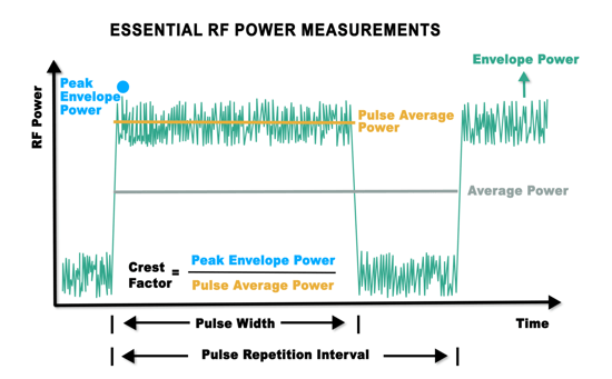
- Envelope power: Amplitude variations from modulation or distortion as a function of time averaged over one or a few cycles of the RF carrier signal.
- Peak envelope power (PEP): The maximum point or peak amplitude of the envelope power.
- Average power: The average power level over the pulse repetition interval (PRI), which includes the signal burst and the interval before the next pulse.
- Pulse average power: The average power level of the signal burst.
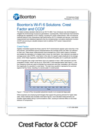
- Crest factor: Also referred to as the peak-to-average power ratio (PAPR), crest factor can be defined as the ratio of the PEP over the average power or pulse average power.
 💡For more information on the distinctions between essential power measurements, read the article, "What Do You Want to Measure – Peak or Average?"
Peak power sensors have triggering capabilities, which allow them to synchronized pulse measurements. When choosing a peak power test solution, engineers should consider a sensor's video bandwidth to accurately track a signal's envelope power, rise time to capture a pulse's rising edge, time resolution to verify pulse shape and timing, and crest factor/statistical measurements to assess component linearity.
Video bandwidth and the ability to track a signal's profile are less of a concern when selecting an average power sensor, since these instruments are only used to measure average power over time and instantaneous envelope results are not required.
Leading the Way in Testing RF & Microwave Power
Offering leading performance, Boonton RTP5000 Series Real-Time USB Peak Power Sensors deliver 16 automated pulse measurements, crest factor and statistical measurements, wide video bandwidth at 195 MHz, quick 3 nanosecond rise times, and superior 100-picosecond time resolution.
With a frequency range down to 4 kHz, the RTP4000 Series provides accurate true average power measurements virtually independent of signal modulation bandwidth.
Some notable features of the RTP family of RF power sensors include:
- Real-Time Power Processing (RTPP)
- Lightning-fast measurement rate at 100,000 measurements per second
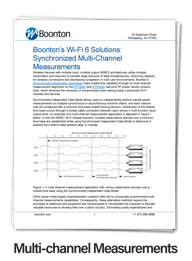
- Synchronized multi-channel measurements
- Compatibility with the PMX40 RF Power Meter
RTPP technology breaks the latency limitations of conventional test systems. Used to create a signal trace on a display, waveform samples are captured and processed in parallel to the acquisition with RTPP. Standard techniques pause signal acquisition to perform these processing steps sequentially. This gap is where critical waveform events can occur unnoticed. RTPP eliminates long acquisition gaps and captures what conventional test systems often miss.
This unique approach to digital signal processing works in conjunction with the Boonton RTP Series Measurement Buffer Mode Application to enable extended measurement windows.
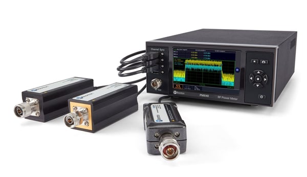
While the RTP sensors can connect via USB to a computer loaded with analysis software such as the Boonton Power Analyzer, they are also compatible with the Boonton PMX40 RF Power Meter for a dedicated benchtop experience.
Addressing RF Communications & Radar Measurement Challenges
Boonton state-of-the-art RF power measurement tools provide the capabilities needed to address complex testing challenges for applications such as radar and Wi-Fi 6/6E.
Secondary Surveillance Radar Analysis
Used for air traffic control (ATC), secondary surveillance radar (SSR) sends interrogation signals toward aircraft of interest that are equipped with an onboard radar transponder to transmit encoded replies. ATC can determine different pieces of information with SSR, such as an aircraft’s identification code or altitude, depending on the mode of the interrogation signal.
The extremely fast rise times of the RTP5000 Series can track the leading edge of narrowly spaced SSR pulses cleanly, while fine time resolution enables engineers to examine SSR pulse shape and timing.
Radar systems must operate reliably to maintain the integrity and safety of aviation. Therefore, long-term, real-time, gap-free monitoring is critical to detect signal anomalies. For instance, the heat from the high RF power level of SSR systems can affect power amplifiers, ultimately causing power droop or dropout. Long measurement intervals can uncover these important waveform events.
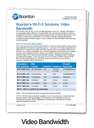
Wi-Fi 6/6E Test Solutions
Wi-Fi 6 (802.11ax) is the latest generation of the Wi-Fi standard that is designed to improve efficiency and speed in dense wireless environments. The PMX40 and RTP RF power sensors can overcome complex Wi-Fi 6 testing challenges, optimizing measurement accuracy, ease-of-use, and cost.
Wi-Fi 6 utilizes wide channel bandwidths, such as 80 MHz and 160 MHz. With the widest video bandwidth available at 195 MHz, the RTP5000 Series can capture the true peaks of a Wi-Fi 6 signal without clipping or compromises. Wi-Fi 6E extends the operational frequency range to 7.125 GHz.
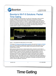
With 1,992 sub-carriers using up to 1024-QAM, Wi-Fi 6 signals often have high crest factor values. Boonton solutions offer crest factor measurements and statistical analysis to assess component linearity. Additionally, users can easily test a Wi-Fi signal over extended time periods, target specific sections of a Wi-Fi signal via markers or time gating, and capture multi-channel RF power measurements.
Learn more about Boonton Wi-Fi 6 test solutions in our five-part article series: