Applications such as radar and communication systems rely on the control and manipulation of...
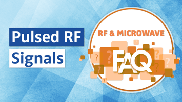
How do pulsed-modulated RF signals differ from continuous wave (CW) signals? What are some defining pulsed signal characteristics and which instruments are best to analyze their behavior? Uncover the answer in the blog post below.
Pulsed-modulated RF Signals
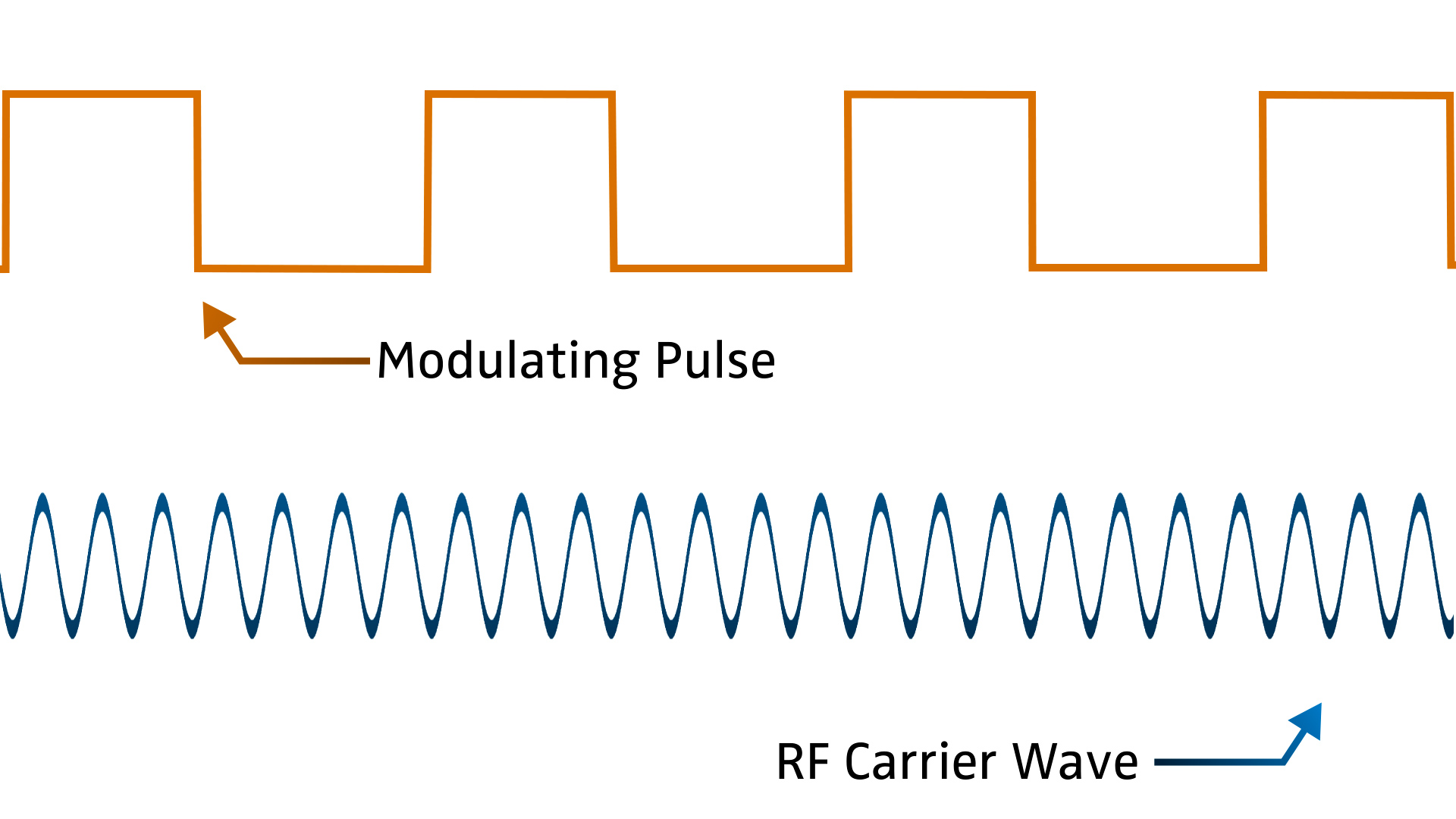
RF carrier waves are changed or modulated by some sort of signal that holds information. They are used to carry data during transit. After over-the-air (OTA) transmission, the receiving system demodulates the signal to recover the data. Carrier waves are typically sinusoidal, which is a type of CW signal that has a constant amplitude and frequency.
A pulsed signal alternates between “on” and “off” states. When a pulse modifies an RF carrier signal, the carrier’s behavior changes from consistent emission to periodic bursts. Pulsed-modulated RF signals are widely used in pulsed radar applications. After transmitting a pulsed signal, the radar receives the delayed pulse reflected back from the target.
A caption that describes the image.
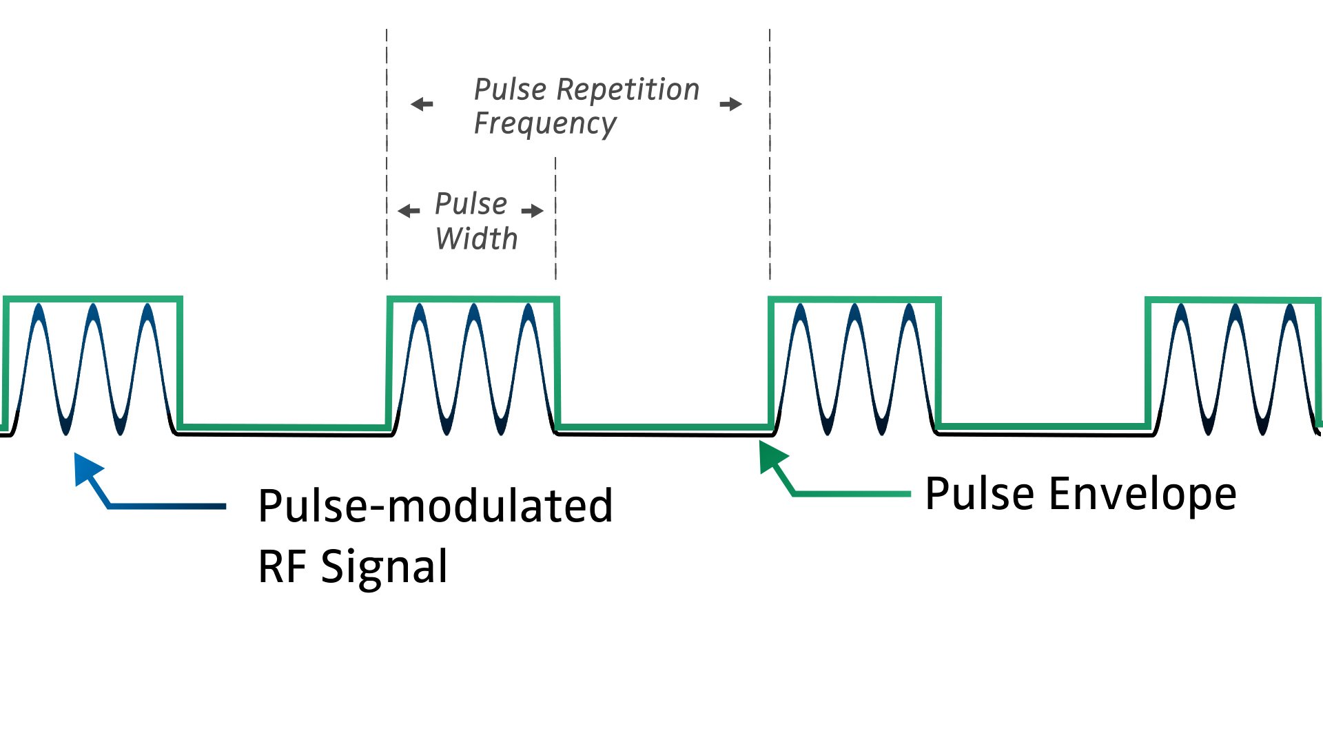
A pulse-modulated RF carrier signal
Pulse repetition frequency (PRF) is an important radar parameter. It defines the maximum unambiguous range of a target. Radar systems with short-range targets require shorter off periods and higher PRFs, while longer off periods and lower PRFs are necessary for distant targets to avoid range ambiguity.
The pulse envelope is a trace of the change in amplitude or shape of each pulse. An ideal pulse envelope is completely rectangular with vertical leading and trailing edges. Real-world pulsed RF signals do not exhibit this ideal behavior and experience distortions that can impact performance.
Important Pulsed Signal Characteristics
Leading and trailing edges that are perfect vertical lines equate to a rise time and fall time of zero. Real-world pulses, however, have a non-zero rise time from 10% to 90% of the pulse magnitude, and vice versa for the fall time of the trailing edge.
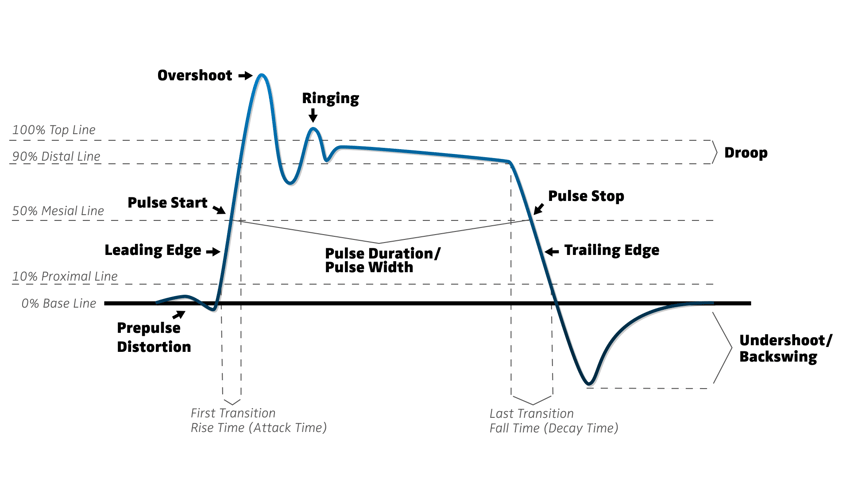
Overshoot immediately follows the leading edge, where the waveform surpasses the desired value. Undershoot is its counterpart in the opposite direction, occurring right after the pulse’s trailing edge. After exceeding its target via overshoot, the signal experiences unwanted oscillations or ringing artifacts before reaching its steady-state value.
In theoretical conditions, the pulse’s power remains constant immediately following a zero rise time. This gives an ideal pulse its flat-topped, rectangular appearance. Amplitude, however, may reduce between the beginning and end of the pulse due to amplifier thermal effects. This is referred to as droop.
Pulses that are “on” for long periods of time are more susceptible to pulse distortions such as droop, which ultimately affect system performance. For example, next-generation radar systems transmit long pulse width signals. Range and receiver target acquisition time will reduce if the highest level of waveform fidelity isn’t maintained.
The article, “Innovations in Pulse Fidelity for High-Power GaN Radar and EW Transmitters,” which is featured in the Microwave Journal March 2023 Test And Measurement issue, reviews how to reduce pulse distortions in high-power transmitters used in advanced radar and EW systems. Read about how droop and overshoot impact radar performance, real-time pulse corrections, and a test demonstration using an Empower RF Systems Inc. 40 kW pulsed transmitter and Boonton peak power sensors.
Pulsed Measurements with Peak Power Meters
As opposed to the frequency domain, many measurements critical to understanding the behavior of RF pulses and their impact on amplifier performance are conducted through time domain signal analysis.
Peak power meters and USB peak power sensors are ideal instruments for time domain power measurements. When detecting a pulsed RF signal, the power sensor must respond fast enough to capture the pulse’s leading edge, which increases the importance of the sensor’s rise time capabilities. In addition, video bandwidth (VBW) defines a sensor’s ability to accurately track a pulse’s envelope power. Narrow VBW will affect the accuracy of several measurements, including envelope power, peak envelope power, pulse average power, and average power.
The Boonton RTP5000 Series sensors, for example, can track fast, complex, and narrowly spaced RF pulses. Key specifications include:
- Rise time: 3 nanoseconds
- Video bandwidth: 195 MHz
- Measurement speed: 100,000 per second
- Time resolution: 100 picoseconds
- Minimum pulse width: Ability to make measurements on pulses as narrow as 10 nanoseconds
Featured on Microwave Product Digest (MPD) is the Wireless Telecom Group article, “Peak Power Meters: Essential Instruments for Radar Power Amplifier Measurements.” Readers will learn even more insight into why peak power meters are vital tools for characterizing the performance of high-power radar amplifiers.